Graphs
A graph is the term used to describe the collective visual logic you create in uScript on the Canvas. A single graph can have many separate sections of visual logic that are used to do a variety of things while the game is running. A uScript graph is all the logic that is contained within a single uScript file (*.uscript) you have created with the uScript Editor. Another words, each uScript file you make is considered a uScript graph.
Common usage examples include:
"Load up the graph and let's take a look at the logic."
"Save the graph and run the game to see what happens."
"You need to re-save your graphs using debug mode so we can use breakpoints."
Anatomy Of A Graph
A uScript graph is made up of several different "parts" that are used in combination to create a graph:
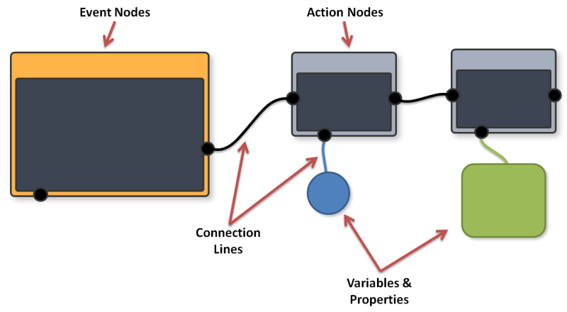
Nodes - Almost everything you can put on a graph in uScript is considered a "node". While there are many different types of nodes (see "Nodes" for more information on the different types of nodes), there are a couple of critical types required to make working logic in a graph:
Event / Action Nodes- In order to have a working graph, you must have at least one Event node (orange) and one Action node (gray) connected together. All graph's must contain at least one Event node to execute graph logic.
Variable / Property Nodes- These are nodes that hold information/data. While you can make very simple graphs without them, you will most likely want to have Variables of some type so you can use external data from your Unity project. See "Variables" for more information on these types of nodes.
Connection Lines - All nodes must be connected together by Connection Lines in order to function/be accessed. There are two types of Connection Lines:
Signal Connection Lines - These connection lines go between the Input and Output sockets on the left/right sides of Event and Action nodes. Think of these as electric wires that are used for activating the nodes in the chain by sending a signal along the wire that action nodes are listening for.
Data Connection Lines - These are lines that connect your variables and properties to the variable sockets on Event and Action nodes. They tend to be color coded the same as the variable type they use. These Connection Lines will read or write data to connected Variables and Properties depending on if they are hooked up to a Variable Input (read) or Variable Output (write) socket on the node.
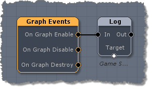
Here is an example of the smallest functioning graph you can make in uScript. It prints "Game Started!" once to the Unity console when run:
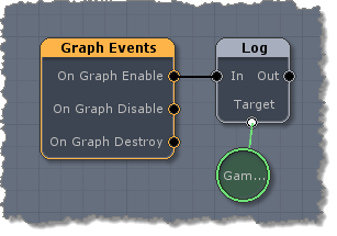
And here is the same logic, just using an external string variable node instead of specifying the "Game Started!" text directly in the Log node:
Understanding "The Signal"
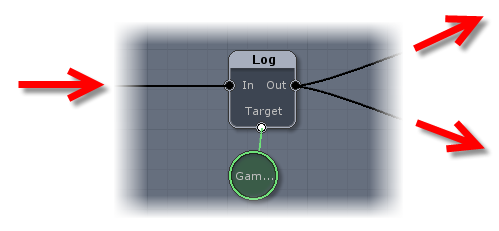
Creating visual scripts means hooking up nodes that perform very specific functions and logic in complex ways to create anything you could imagine. This is done by connecting the nodes together using Connection Lines. This allows nodes to both receive and send signals when you wish them to. The easiest way to think of these Connection Lines are as wires that will send electricity along them, powering the action nodes to do their thing.
uScript graph logic, and the signals is sends to other nodes, is done from left to right. This means that all nodes will listen for signals from Connection Lines hooked up to their Input sockets on the left side of the node and send out signals along Connection Lines hooked up to their Output sockets on the right side of the node.
You can control when a signal is sent in several ways:
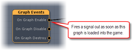
Event Nodes - All uScript logic that executes must start at some point from an Event Node. Event nodes listen for things to happen in your game and will fire off a signal whenever its specific criteria is met (like entering a specific trigger, loading a scene, pressing a button, etc.). Notice that Even nodes do not have In sockets on them. This is because they are the ones that start signals that are then sent to Action nodes. You can also think of the as the energy source of the electricity.
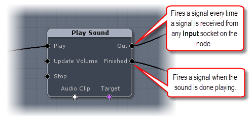
Action Nodes - Action nodes contain Out sockets that will pass along a signal. If and when this signal is passed along, depends on the conditions of the socket. For example, nodes with an "Out" socket will always pass along any signal it receives to that socket as soon as it gets the signal, where something like the "Finished" socket on the Play Sound node will only fire a signal out once the audio is done playing. See the description in the Reference Panel for each node to learn more about when any given node's different Out sockets will fire.
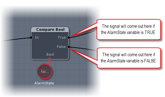
Condition Nodes - Condition nodes are just Action nodes that are used specifically to control signal flow from Connection Lines in useful ways commonly used when creating logic flow. They can also be used in combination to create very complex and powerful criteria to determine where and when a signal should be allowed to continue.
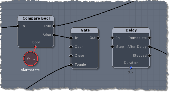
Using Condition nodes in combination for more complex signal control if AlarmState is FALSE by also checking to see if a gate is open (toggled between open and closed by other logic in the graph), and if so, then also waiting for 3.5 seconds before allowing the signal to continue on:
Frequency Of The Signal
How frequently a signal is sent out from an Event or Action nodes depends on the kind of node it is and the type of logic that node is executing. It is important to understand exactly how often a signal is sent and also how action nodes will react to getting multiple signals to avoid unexpected results form your logic.
Typically, when a signal will be sent by a specific Output socket on a node fall into one of three categories:
Once - In many cases, only one signal will be sent at a time-- either right when a signal/event is received by the node, or after a delay based on other functionality/criteria of the node. We try to follow this paradigm as much as possible, though there are still many nodes that need to send a signal more frequently than this.
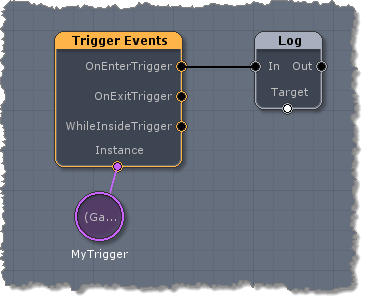
Here is an example of an event node that will only send out a single signal to the Log node each time something enters the MyTrigger trigger:
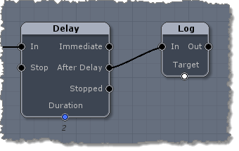
Here is an example of an Action node that will send a single signal to the Log node after a 2 second delay for each time it receives a signal on its "In" Input Socket:
Once Per Tick/Time - The second most common case is that a signal is sent out repeatedly by a node based on every tick of the game (OnUpdate), or based on some other factor of time (seconds, frames, etc).
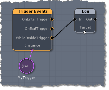
Here is an example of that same MyTrigger trigger. It will fire out a signal every tick of the game to the Log node as long as something is inside the trigger:
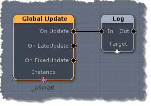
Here is an example of another Event node that will send a signal every tick of the game to the Log node:
Once Per Iteration/Cycle - Some action nodes have Output sockets that will send out a signal each time something specific happens within the node while executing logic or iterating on multiple things when it receives just a single signal on its Input socket.
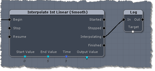
Here is an example of an Action node that will send out a signal to the Log node every time it changes the Output Value while interpolating-- even though it only received a single signal on its "Begin" Input socket to start the node executing:
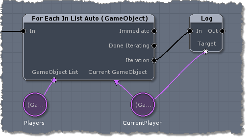
Here is an example of a For Each node iterating through all the players in a GameObject List variable. A signal is sent to the Log node once for each GameObject in the Players variable (where it prints that specific GameObject to the Unity console via the CurrentPlayer variable):
Execution Order
Sometimes it can be important to know exactly WHEN signals will reach a node and how to ensure that nodes are executed in the proper order.
Let's take a look at this example logic:
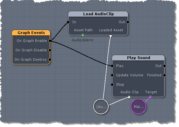
Notice how there are two separate Connection Lines coming off of the Event node? This means that a signal will be sent down each Connection Line to its respective nodes when the game starts. Unfortunately uScript has no way of knowing in this case which node will be executed first by Unity since we just told Unity to "do both these things when you get a chance".
This means we could end up with a case where Unity is trying to play the sound using the AudioClip variable before we have had a chance to assign it with the "alarm" sound! We might get lucky and they will execute in the correct order-- but it would not be safe to leave it like this and could cause unwanted bugs later.
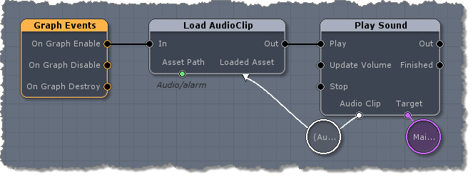
It is best to ensure the order of execution by linking these nodes in the order we want them to execute in. By rearranging how this logic is hooked up, we can tell Unity to "please load the sound first and then play it":
While the above example is a pretty simple one, you may very well run into more complex setups in large graphs of logic. Make sure you keep an eye out for cases where you might be trying to execute some logic before some other critical logic was executed.
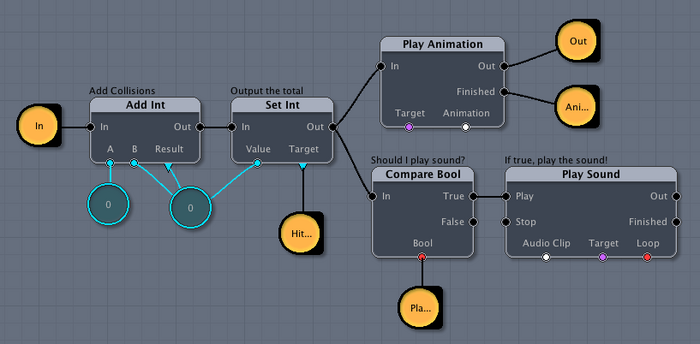
Here is another example where execution order would matter:
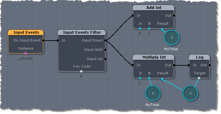
In the above graph you can't be sure if the MyTotal named variable value will be 0 or 5 when the Multiply node executes. This means you might get either "0" or "10" printed out to the Unity console.
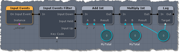
To ensure the answer is always "10", you should fix the logic to force the order of execution:
Graph Types
While there are no hard rules in how you use uScript, there are three primary types of graphs that you create with uScript to execute visual scripting logic-- Scene Graphs, Prefab Graphs, and Nested Graphs.
Scene Graphs
Creating a single uScript graph for your scene to perform gameplay logic is the basic way in which you use uScript. In many cases, it is fine to just have one uScript graph for each of your Unity scenes (levels) as you can manage most of your gameplay logic in this way.
That graph is usually assigned to the uScript master GameObject that it creates for your scene. Because uScript handles things within its graph, you don't end up with a lot of components and scripts cluttering up your scene's individual GameObjects.
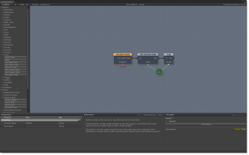
Here is an example of a very simple scene graph:
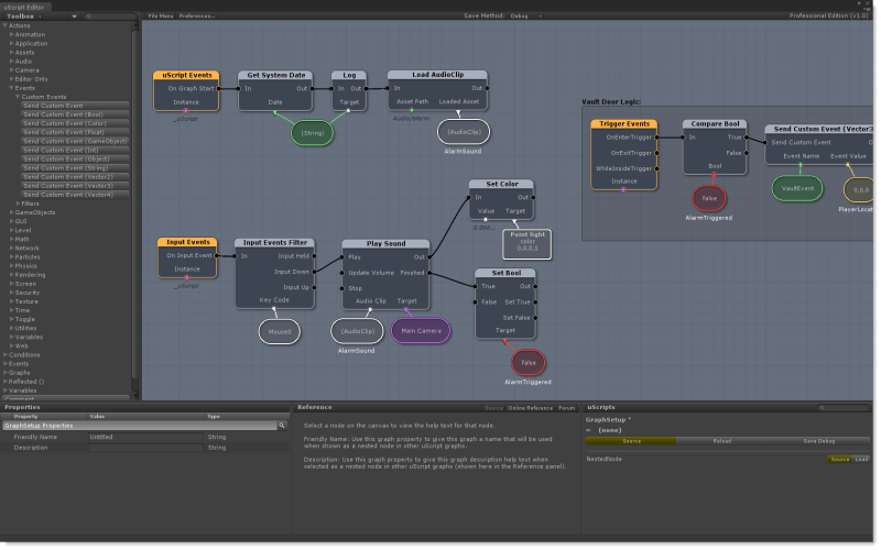
Here is the same uScript graph with more complex logic added to it:
Prefab Graphs
Just like the name implies, these are uScript graphs that you can place on a prefab GameObject which will be spawned into your game at runtime. These graphs are very powerful and allow you to handle GameObject-specific logic on the GameObject/prefab itself. An example of this could be shooting a missile into the world or simple logic that opens and closes a door prefab that is placed throughout your game levels.
Your main gameplay uScript graph would be responsible for spawning the missile when the player hits the fire button for example, but once it is spawned you may have missile-specific logic you want to have on the missile itself so that when it collides with something it will play particle effects, sounds, add explosion forces all by itself-- and then destroy itself from the scene when it is done.
This means each instance of the prefab you spawn in the world will automatically run its own uScript graph logic and you don't have to worry about keeping track of them individually in the main uScript gameplay graph.
In order to create uScript graphs for prefabs, you will want to use the special "Owner GameObject" variable whenever you need to assign a node's Instance property to the prefab. This special variable tells uScript to use whatever GameObject the uScript graph is assigned to.
Note! - for those of you more familiar with scripting, the Owner GameObject variable is the equivalent of "this" in many programming languages. It simply tells uScript "Use whatever GameObject this graph's script component is on.".
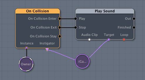
Here is an example Prefab Graph using the Owner variable:
Nested Graphs
uScript can also be used in another way to help organize and extend the functionality of uScript itself by letting you create your own custom nodes right from within uScript. Special uScript graphs can be created that will allow non-technical users to take complex visual logic and create their own custom action node from it. We call these Nested Graphs because all the complexity of the graph is hidden away behind a single node that is then used in other uScript graphs.
Another way to think of them are as recipes that perform a task that you may want to reuse in different parts of your project or even in completely different projects. You can very easily build up a library of these recipes for yourself and to share with other team members or on the http://www.uscript.net.
In order to make input/output/variable sockets appear on the nested uScript node on your graph, you need to use External Variables within the nested uScript hooked up to the sockets you wish exposed. By using these and naming them, they will create sockets on the nested uScript node.
Here is an example of creating a Nested uScript saved as "Nested_Example.uscript":
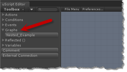
Graphs that contain External Connection nodes will appear in the "Graphs" section of the Nodes Palette and can be placed as nodes in other graphs. The "Graphs" section will not appear if no uScript graphs in your project contain an External Connection:
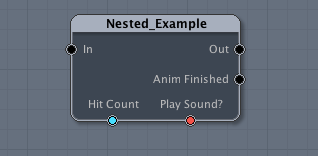
And here is what the node created from the nested graph looks like when placing it inside another uScript graph:
Graph Properties
Graphs have some properties that you can set on them. These properties are not really used by uScript unless you are making a Nested Graph (see Nested Graphs in this section).
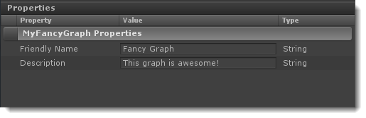
Friendly Name - This lets you set a friendly name for the graph that will be used as both the node title and at the top of the Reference Panel when the nested graph appears as a node on other graphs.
Description - This lets you set a description that represents the nested graphs functionality. This will be displayed in the Reference Panel when the nested graph appears as a node on other graphs and is selected.
Saving Graphs
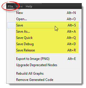
Saving your graphs is fairly straightforward. To save the currently open uScript graph, just go to uScript's File Menu above the Canvas and choose the save option you wish to use (also note the Save hot-keys assigned to each save option for fast access to the save features).
Note! - Using Unity's File menu Save Scene option (or the Ctrl+S hot-key for this option), will NOT save your uScript graph-- just the open Unity scene. You must use one of the save options or hot-keys inside of the uScript editor as mentioned here to save your graph.
Optionally you can press the Save button in the uScripts Panel, shown here:
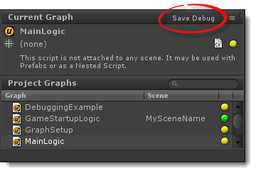
When saving your uScript graphs, you have three options in how you wish to save:
Debug - This is the default save method and allows you to use uScript's advanced debugging options such as setting breakpoints in your graph logic. Files saved as debug tend to generate slightly larger script files because of the extra debug code added when the scripts are generated.
Release - This creates the most optimized and smallest file size. You should use this save method when you are ready to ship your software. Please note however that you can not use the breakpoint debugging features for files saved this way as all the debug support code has been removed from the generated script files.
Quick - This allows you to very quickly save just your main .uscript graph file without regenerating the script code (and therefor avoiding Unity's automatic recompiling of all scripts). This can be handy when you just want to make sure you are saving your work while in the middle of graph editing. Please note however that since uScript is not regenerating the actual script code from changes you are making, you will not see these changes when you run the game until you have done a full debug or release save of the graph.
Saving to the uScript Master GameObject
When saving a new uScript graph for the first time and generating its script, it will ask you if you wish to assign that graph's generated script component to the Master GameObject.
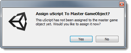
Whether you wish to assign this new graph's generated script to the Master GameObject really depends on the type of graph you wish to create (see above).
Yes - Select "Yes" if you are creating a typical Scene Graph where you don't care what GameObject the graph is assigned to. and you wish to have easy access and management of your scene graphs by having them assigned to the same GameObject. Any graph that you choose "Yes" for will also remember the name of the Unity Scene it was saved to. This is used to help warn you if you later try to use this graph in another Unity scene. This is done because many scene graphs rely on specific data and GameObjects to exist, and another scene may not have the proper data and GameObjects to allow the graph to function properly. If you are new to uScript and are just making a graph with logic you want to work in your scene at runtime, chances are you want to assign it to the Master GameObject.
No - Select "No" if you are making either a Prefab Graph or a Nested Graph-- or any other time you wish to manually assign the graph to a specific GameObject in your Unity scene.
IMPORTANT! - All uScript graphs must be assigned to a enabled GameObject in your Unity scene in order to run. graphs that are not assigned to a GameObject in your Unity scene will be excluded from Unity when it builds your game.
Manually Assigning Generated Script Components
You can manually assign a uScript graph component to any GameObject in your scene by using Unity's "Component" menu:
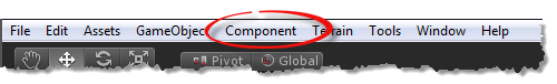
Just open up the "uScript" section of this menu and go to the "Graphs" section:

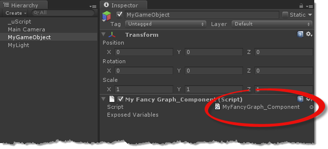
Once the graph's component has been assigned, you can see it in Unity's Inspector panel for that GameObject:
Generating Script Code
When saving your uScript graph files, uScript will automatically generate pure C# code files for use by the game at runtime (unless you choose the "Quick" save method). While there is nothing you need to do or worry about regarding these generated code files, you will see that Unity will recompile all scripts once the new or updated script file has been generated by uScript. This is normal and Unity's default behavior whenever a change, edit or deletion of a script file in the project has been made.
The full order of operations when saving a uScript graph are as follows:
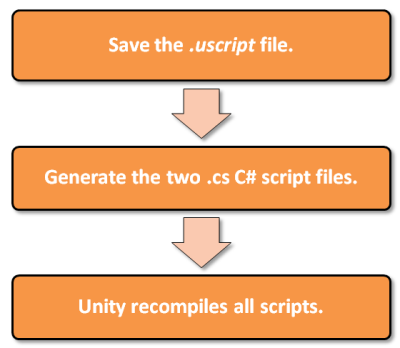
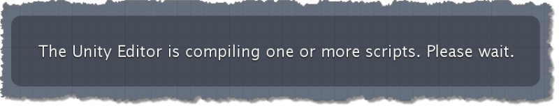
Whenever Unity is compiling scripts, you should see the following message in the uScript Editor window. Just wait for Unity to finish and this message to go away before continuing to use the uScript Editor:
Also see "Script Generation".
Using the Graphs Panel
You can quickly view your projects existing uScript graphs by browsing them in the uScript Panel form within the uScript editor. This panel allows you to view, load and save your project's uScript graphs.
Please see the Graphs Panel section of "Editor Interface" for details on this panel.